
Every precision component begins as an idea a functional requirement, a design specification, or an urgent need to replace a failed part in the field. Between that starting point and a finished, inspected, certified component ready for installation lies a sequence of highly controlled engineering and manufacturing steps that most procurement managers and project engineers never fully see.
Understanding this process matters. It helps you ask better questions when evaluating a machine shop, write better purchase orders and technical specifications, set realistic lead time expectations, and identify where quality risks actually live in a production workflow. It also helps you understand why a genuinely capable precision manufacturer like Genesis MFG operates differently from a general fabrication workshop.
This article walks through the complete production journey at Genesis MFG from the moment a CAD file or drawing lands in our inbox to the moment a finished, documented component leaves our Sharjah facility bound for your site.
Step 1: Enquiry Review and Design for Manufacture Assessment
The process begins before a single machine is switched on. When Genesis MFG receives a new enquiry, our engineering team conducts a thorough review of the drawing package or CAD files provided. This is not a passive file receipt it is an active technical assessment.
Our engineers examine every aspect of the design from a manufacturability perspective. We ask: Can this geometry be reliably machined with the tolerances specified? Are the surface finish callouts achievable with the selected material? Are there features that could be redesigned slightly to reduce machining time or risk without compromising function? Is the material specified appropriate for the operating environment?
This design for manufacture (DFM) review stage is where significant value is created for clients. A drawing that looks complete on paper may contain features that are extraordinarily difficult to hold to tolerance in practice deep internal threads, very thin walls, blind holes that require special tooling, or geometric callouts that require multi-axis fixturing. Identifying these early, before a production order is raised, prevents costly surprises mid-run.
Where our review identifies potential issues, we raise a technical query with the client before proceeding. This collaborative approach is fundamental to our process and is one of the clearest indicators of a machine shop that genuinely understands manufacturing as opposed to one that simply accepts orders and hopes for the best.
Step 2: Material Selection and Procurement
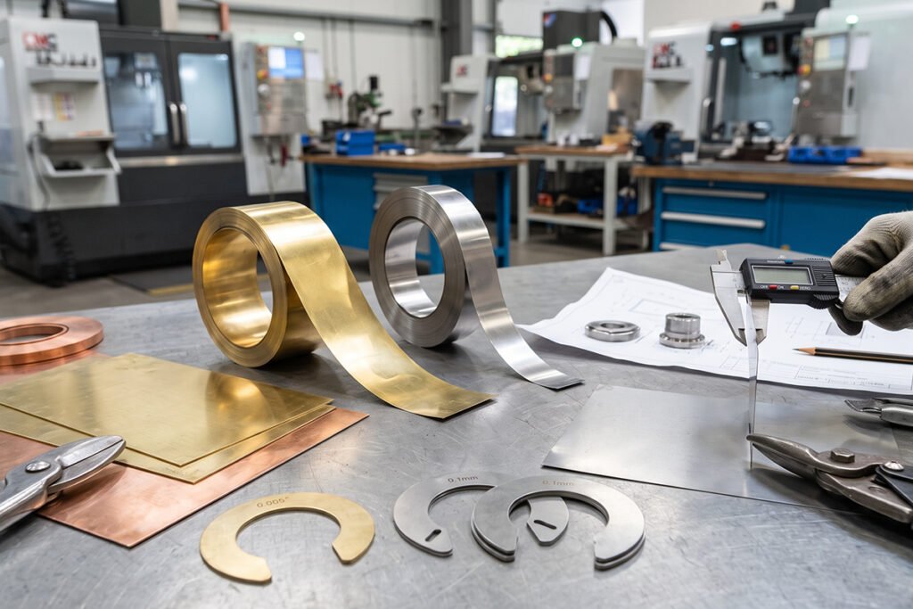
Once the design review is complete and the order is confirmed, material procurement begins. For standard engineering materials carbon steel, stainless steel grades, aluminium alloys, engineering plastics Genesis MFG maintains approved stock from certified suppliers. For specialised alloys such as Inconel, Duplex and Super Duplex stainless, titanium, or Monel that are common in oil and gas and aerospace applications, material is sourced to order against the specific project requirement.
Every material procured for a production order at Genesis MFG must be accompanied by a certified mill test report (CMTR) that documents the chemical composition, mechanical properties, and heat treatment condition of the material. This documentation is the foundation of the material traceability chain that our API Q1 certification requires us to maintain.
Incoming material is inspected on receipt. Dimensions are verified against the purchase order. Mill certificates are checked for compliance with the specified material standard. The material is then given a unique identification marking and logged into our material management system. From this point forward, the material’s identity travels with it through every stage of production.
Step 3: CNC Programming and Toolpath Simulation
With material confirmed and the production plan in place, our CNC programmers develop the machining strategy using advanced CAD/CAM software. This is one of the most technically demanding stages of the process and one that is often invisible to clients.
The programmer begins with the 3D CAD model or, where only a 2D drawing is provided, reconstructs the geometry in CAD. The manufacturing strategy is then developed deciding the sequence of operations, the machine or machines that will be used, the fixturing approach, the cutting tools, and the cutting parameters (speeds, feeds, depths of cut).
For complex components, the toolpath is run through a simulation environment before any physical machining begins. This simulation checks for tool collisions with the workpiece or fixture, verifies that all required features can be reached with the available tooling, and provides an accurate cycle time estimate. Catching a collision or an unreachable feature in simulation costs minutes. Discovering the same problem on the machine costs hours and potentially a scrapped billet of expensive material.
The finished CNC program is then reviewed and approved before being released to the shop floor. For first-time components or high-value materials, a dry run running the program with the spindle off to check motion paths may be performed as an additional verification step.
Step 4: Workholding, Setup, and First Article Inspection
Machining setup is one of the most underappreciated sources of quality risk in precision manufacturing. A component that is not held rigidly and accurately in the machine cannot be machined to tight tolerances regardless of how good the program or the machine is. Fixture design and setup discipline are therefore critical process steps.
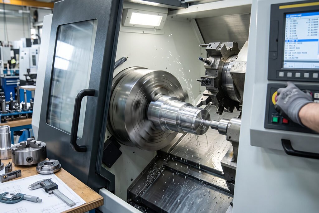
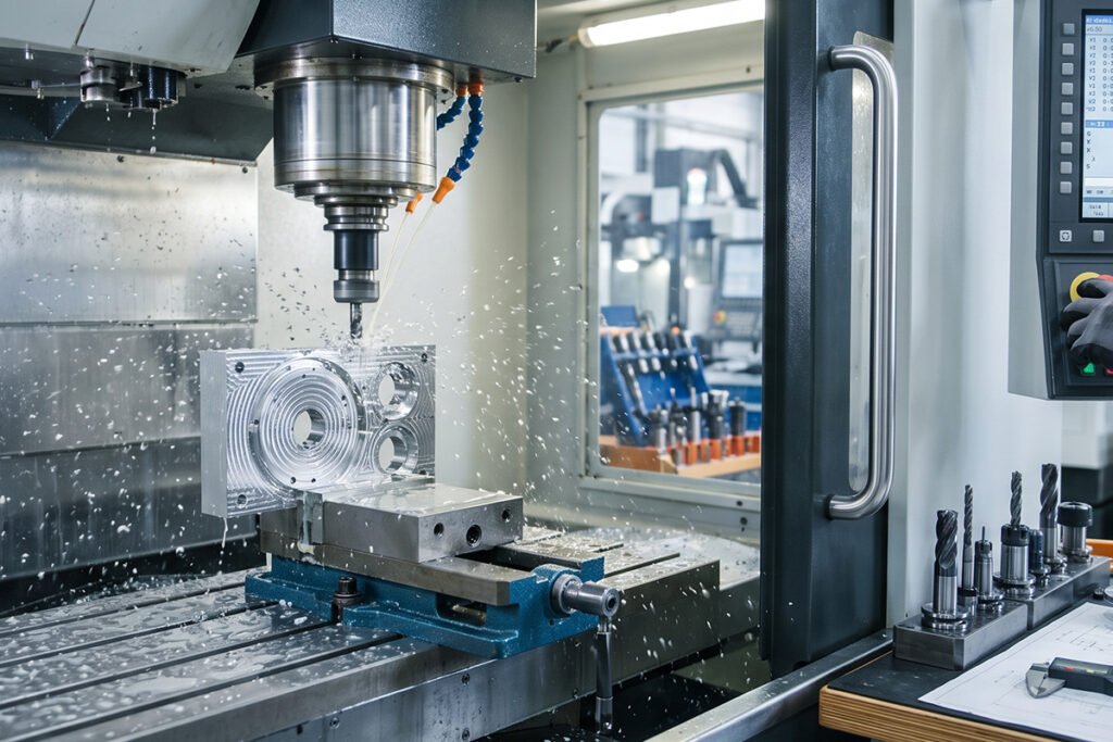
For standard components, proven workholding solutions vices, chucks, collets, and standard fixture plates are used. For complex or high-precision components, custom fixtures may be designed and manufactured specifically for the job. Zero-point clamping systems allow rapid, repeatable repositioning of workpieces between operations with sub-micron repeatability.
Once the first component of a production run is machined, it goes through a first article inspection (FAI) before the rest of the batch is produced. Every critical dimension specified on the drawing is measured using calibrated instruments coordinate measuring machine (CMM), height gauges, bore gauges, thread gauges, surface finish profilometers as appropriate and the results are recorded.
If the first article passes all dimensional checks, production continues. If any dimension is out of tolerance, the setup is adjusted, the cause is investigated, and a new first article is produced and re-inspected before the batch proceeds. This discipline at the first article stage is what prevents an entire batch of non-conforming parts from being produced and discovered only at final inspection.
Step 5: Production Machining and In-Process Inspection
With the first article approved, batch production runs under the control plan established during production planning. In-process inspection is carried out at defined intervals not just at the beginning and end of the run. This is particularly important for longer production runs where tool wear can cause gradual dimensional drift.
Our machinists are trained to monitor key dimensions throughout the run and to escalate immediately if measurements begin trending toward the tolerance boundary. Statistical process control (SPC) principles inform our approach: catching a trend before it becomes a non-conformance is far less costly than discovering out-of-tolerance parts after the fact.
Secondary operations turning after milling, drilling after turning, threading, deburring, and cleaning are completed in the sequence defined by the manufacturing plan, with inspection checkpoints at each stage transition. For multi-operation components, intermediate dimensions are verified before moving to the next operation, since some features become inaccessible for measurement once subsequent machining is complete.
Step 6: Surface Treatment and Secondary Processes
Depending on the application, finished machined components may require secondary processes before final inspection. These can include heat treatment to achieve specified mechanical properties, surface treatments such as hard anodising, electroless nickel plating, or phosphate coating for corrosion or wear resistance, and specialist processes such as passivation for stainless steel components used in corrosive service.
Genesis MFG manages these secondary processes through our network of qualified sub-suppliers. Each sub-supplier is assessed and approved through our supplier qualification process, and their work is subject to incoming inspection when parts are returned. Documentation from secondary process providers heat treatment records, plating thickness certificates, passivation compliance statements is incorporated into the final quality documentation package.
Step 7: Final Inspection and Quality Documentation
Final inspection is the last verification gate before a component is released for shipment. At this stage, the complete set of dimensions specified on the drawing is verified on a representative sample (or 100% inspection for critical components), all surface finish requirements are confirmed, and the cosmetic condition of the part is assessed.
The quality documentation package assembled for each order typically includes:
• Dimensional inspection report with actual measured values against drawing requirements
• Material traceability record linking the finished component to the original mill certificate and heat number
• Certificate of conformance (CoC) signed by our quality manager, confirming the component meets all specified requirements
• Records of any secondary process operations (heat treatment, surface treatment, NDT)
• Non-conformance records, if applicable, with disposition and corrective action details
For clients who require it, witness inspection by a third-party inspector or client representative can be arranged at our Sharjah facility. We also support customer-specific documentation requirements PPAP packages, first article inspection reports to AS9102 format, or custom quality record formats specified in the purchase order.
Step 8: Packaging, Preservation, and Delivery
The final stage before shipment is packaging and preservation. Precision-machined components can be damaged by inadequate packaging machined surfaces scratched, threads damaged, or corrosion initiated during transit. Our packaging standards require that critical surfaces are protected with appropriate materials, components are secured against movement within their packaging, and moisture control measures are applied where required by the material or operating environment.
Delivery is coordinated with the client’s logistics requirements. For urgent requirements, we support expedited dispatch through established freight partners across the UAE and internationally. All shipments are accompanied by the complete quality documentation package.
Why the Process Matters as Much as the Machine
It is tempting to evaluate a machine shop purely on the basis of its equipment list the number of CNC axes, the size of the machining envelope, and the age of the machines. Equipment matters, but it is the process that surrounds the equipment that determines whether a machine shop consistently delivers components that perform in the field.
At Genesis MFG, every step described in this article is documented, controlled, and audited both internally and by our ISO 9001 and API Q1 certification bodies. Our clients in the oil and gas, aerospace, and industrial sectors across the UAE and MENA region choose us not only because we have the technical capability to machine their components, but because they can trust the process that delivers them.
If you have a precision machining requirement whether a single prototype, a replacement part needed urgently, or a volume production order — we invite you to share your drawing or CAD file with our engineering team. We will review your requirements, provide technical feedback where it adds value, and give you a clear, detailed commercial proposal.